Motion sensors
Waveshare boards have on their shared I2C bus, plus whatever magnetometer happens to be wired to it. A script starts it with one call and then does nothing but render state.
This page is the reference for that module — how the subscription works,
what the readings mean, and which of the four boards actually has the part.
For the lower-level sys.gpio / sys.i2c contract see
hardware-api.md; this page cross-references it
rather than repeating it.
- Starting the module
- The subscription: patches, not polling
- The shape of a patch
- What the fleet actually carries
- Ranges and scale factors
- The magnetometer layer
- Axes are not the display’s axes
- Developing with no hardware
- Raw pins and raw bus
Starting the module
Section titled “Starting the module”Modules are a runtime registry. What is compiled in is decided by build
flags; what is running is decided by JS. sys.mods() lists them,
sys.modCtl(name, action) starts and stops them
(firmware/esp32/filament-rfid-bridge/modules.h).
The IMU is registered not running — starting a sensor is the script’s
call, not the firmware’s (mod_wiring.h):
modRegister("imu", false, imuStart, imuStop, imuTick, imuStatus);So the app’s opening line is a start, guarded like every other native:
var HAVE_IMU = typeof sys !== 'undefined' && typeof sys.modCtl === 'function' && sys.modCtl('imu', 'start') === 1;sys.modCtl returns 1 accepted, 0 unknown or failed, and it is
asynchronous: acceptance is immediate, readings arrive later as state
patches. Starting an already-running module is 1, not an error. An unknown
name is 0. imuStart() probes for the chip and returns false when there is
nothing there, so a 0 on the 1.47” board is the honest answer rather than a
silent no-op:
static bool imuStart() { const uint8_t tryAddr[2] = { 0x6B, 0x6A }; g_imuAddr = 0; for (int a = 0; a < 2; a++) { uint8_t who = 0; if (i2cRd(tryAddr[a], 0x00, &who, 1) == 1 && who == 0x05) { g_imuAddr = tryAddr[a]; imuWr(0x02, 0x40); // CTRL1: address auto-increment imuWr(0x03, 0x04); // CTRL2: accel +-2g, 250Hz imuWr(0x04, 0x54); // CTRL3: gyro +-512dps, 250Hz imuWr(0x08, 0x03); // CTRL7: accel + gyro enable break; } } magStart(); return g_imuAddr != 0 || g_magAddr != 0;}Note the last two lines: the magnetometer is probed independently, so a board with a wired mag and no IMU still starts. Stop when the view goes away, or the module keeps reading for nobody:
UI.onCleanup(function () { if (HAVE_IMU) sys.modCtl('imu', 'stop');});sys.mods() returns the registry as JSON including each module’s status
body, which is how a page can name the part instead of guessing:
/* What the module found, so the page can name the part rather than guessing: {"addr":107,"imu":"QMI8658","mag":"none",...} */var INFO = {};if (HAVE_IMU && typeof sys.mods === 'function') { var raw = sys.mods(); if (raw && raw.indexOf('QMI8658') >= 0) INFO.imu = 'QMI8658'; var MAGS = ['QMC5883L', 'HMC5883L', 'LIS3MDL', 'MLX90393']; for (var mi = 0; mi < MAGS.length; mi++) { if (raw && raw.indexOf(MAGS[mi]) >= 0) { INFO.mag = MAGS[mi]; break; } }}The subscription: patches, not polling
Section titled “The subscription: patches, not polling”There is no read call. The module’s tick() runs on the firmware’s loop,
and when a reading has moved it pushes a state patch through the same
queue the printer feed uses — UI.patch into UI.state. The app
subscribes by rendering from state and is redrawn when state changes.
sys.modCtl('imu','start') -> imuTick() every loop reading moved? -> jsQueueState(json) -> UI.state.accel -> re-renderTwo gates keep an idle board from becoming a message pump. A 100ms floor:
if ((!g_imuAddr && !g_magAddr) || millis() - lastAt < 100) return;and a per-signal movement threshold, compared against the last value sent:
/* Patch only on real movement, per signal: ~0.02g, ~2dps, 0.5C. An idle board should not be a message pump. */if (abs(ax - lA[0]) >= 320 || abs(ay - lA[1]) >= 320 || abs(az - lA[2]) >= 320) {| Signal | Raw threshold | In units |
|---|---|---|
| accel | 320 LSB | ~0.02 g |
| gyro | 128 LSB | 2 deg/s |
| temp | 0.5 | 0.5 C |
| mag | squared delta > 1.0 | ~1 uT |
The patch carries only the signals that moved — an object with accel
alone is normal, and code must not assume gyro is present in the same
patch. If nothing moved, nothing is sent at all.
This has a consequence worth designing around: a render is exactly when new data arrived. The example’s rolling history is therefore fed from the render rather than from a timer of its own, so the trace advances with the signal and never depends on two clocks agreeing:
function pushSample(a) { /* Fed from the RENDER rather than a timer: a render is exactly when new data arrived (the module patches state only when a reading moved), so the trace advances with the signal and never depends on a second clock agreeing with the first. */ if (!a || a === hist.last) return; hist.last = a; hist.x.push(a.x); hist.y.push(a.y); hist.z.push(a.z); if (hist.x.length > HIST_N) { hist.x.shift(); hist.y.shift(); hist.z.shift(); }}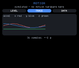
The TRACE view: the last few seconds of each axis as a sparkline, so a tap
or a shake reads as a shape instead of three twitching numbers. x and y are
the two curves, z is the flat line at rest, and the count under the panel
(31 samples) is the history advancing by the patches, not by a poll.
The shape of a patch
Section titled “The shape of a patch”Straight from the module’s header, with the units the JS side receives:
{"accel":{"x":-0.02,"y":0.98,"z":0.11}, g "gyro":{"x":0.4,"y":-1.2,"z":0.0}, degrees/second "temp":31.5, celsius "mag":{"x":12.4,"y":-30.1,"z":44.0}} microtesla| Key | Type | Unit | Precision sent |
|---|---|---|---|
accel | {x, y, z} | g | 2 decimals |
gyro | {x, y, z} | degrees/second | 1 decimal |
temp | number | celsius (die temperature) | 1 decimal |
mag | {x, y, z} | microtesla | 1 decimal |
temp is the IMU die, not ambient — it reads warm and is useful for drift,
not for room temperature. Reading them is ordinary state:
var a = UI.state.accel || null;var g = UI.state.gyro || null;var m = UI.state.mag || null;var t = UI.state.temp;var amag = a ? Math.sqrt(a.x * a.x + a.y * a.y + a.z * a.z) : null;Every one of them can be absent, and absence is a normal answer rather than an error — the example prints what is missing instead of hiding it:
{v ? <row gap={em(0.5)}> <text text={'x' + fmt(v.x, p.d)} size={sz} color={UI.theme.text} /> <text text={'y' + fmt(v.y, p.d)} size={sz} color={UI.theme.text} /> <text text={'z' + fmt(v.z, p.d)} size={sz} color={UI.theme.text} /> </row> : <text text={p.absent || 'not present'} size={1} color={UI.theme.warn} />}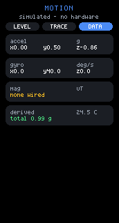
The DATA view on the 1.47” board — the one board in the fleet with no
motion sensor at all. The mag row reads none wired in warn rather than
x0.0 y0.0 z0.0, and the header says simulated - no hardware: both are
the page stating what is absent rather than showing zeros. (none wired is
the short form; a panel 200px or wider gets no magnetometer wired.)
What the fleet actually carries
Section titled “What the fleet actually carries”Measured by scanning all four boards, recorded in mod_imu.h:
| Board | Motion sensor | Also on the bus |
|---|---|---|
| 1.69” 240x280 | QMI8658 at 0x6B | RTC 0x51 |
| 3.5” 320x480 | QMI8658 at 0x6B | codec, I/O expander, PMU, touch, RTC |
| 1.28” round 240x240 | QMI8658 at 0x6B | touch 0x15 |
| 1.47” 172x320 | none | — |
Three facts to design against:
- The 1.47” has no motion sensor.
imuStart()says so rather than lying, and any app that offers a motion feature needs a path for that board. It is not a wiring fault to chase. - No board carries a magnetometer. The whole mag layer below exists for a part wired to the exposed pins.
- 0x7E is not a device. It answers an address scan on three boards but
no register read;
0x78..0x7Fare reserved I2C addresses, so that is a scan artifact.
The probe tries 0x6B then 0x6A and confirms with a WHO_AM_I of 0x05,
so an address hit alone is never taken as a QMI8658.
Ranges and scale factors
Section titled “Ranges and scale factors”The conversion constants and the control registers are two halves of one decision. Change a range and you must change its scale factor:
#define QMI_ACC_LSB_PER_G 16384.0f /* CTRL2 +-2g */#define QMI_GYR_LSB_PER_DPS 64.0f /* CTRL3 +-512dps */| Quantity | Register set at start | Full scale | LSB per unit |
|---|---|---|---|
| accel | CTRL2 = 0x04 | ±2 g, 250Hz | 16384 / g |
| gyro | CTRL3 = 0x54 | ±512 deg/s, 250Hz | 64 / (deg/s) |
| temp | — | — | 256 / C |
CTRL1 = 0x40 turns on address auto-increment, which is what lets the tick
read temperature, accelerometer and gyroscope as a single 14-byte
transaction starting at 0x33 rather than three round trips on a bus
shared with the touch controller. CTRL7 = 0x03 enables both sensors;
imuStop() writes 0x00 there.
±2 g is the practical limit to remember: a sharp tap saturates, so a shake-detector should threshold well below 2 g rather than looking for a peak it may never see.
The magnetometer layer
Section titled “The magnetometer layer”No board in the fleet has one. This exists for a part wired to the exposed
pins — on the round board, for instance, the SH1.0 header brings out
GPIO 15, 16, 17, 18, 21 and 33 (see
hardware-api.md).
Four parts are recognised, identified by WHO_AM_I where the part has one, put into continuous mode, then read as six little-endian bytes. Each scale converts that part’s LSB to microtesla, so the JS side never learns which chip answered:
| Part | Address | Identified by | Scale to uT |
|---|---|---|---|
| QMC5883L | 0x0D | no reliable WHO_AM_I; register probe | 100 / 12000 (8G) |
| HMC5883L | 0x1E | ident register A reads 'H' | 100 / 1090 |
| LIS3MDL | 0x1C or 0x1E | WHO_AM_I 0x0F = 0x3D | 100 / 6842 |
| MLX90393 | 0x0C..0x0F | accepts the burst-start command | 0.150 uT/LSB |
Byte order differs per part and is handled in magRead — MLX90393 is
big-endian and command-driven rather than a register file, HMC5883L returns
X, Z, Y in that order, the other two are plain little-endian XYZ.
Detection is real; the scaling is not verified against hardware. The scale factors come from each datasheet and have never been checked against a physical part, because no such part has been attached. Treat mag readings as correctly shaped and provisionally scaled: directions and relative changes are trustworthy, absolute microtesla values are not, until someone wires a part and calibrates.
Axes are not the display’s axes
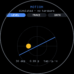
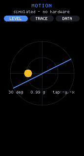
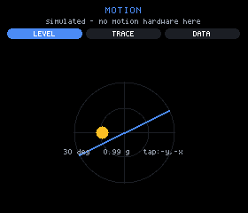
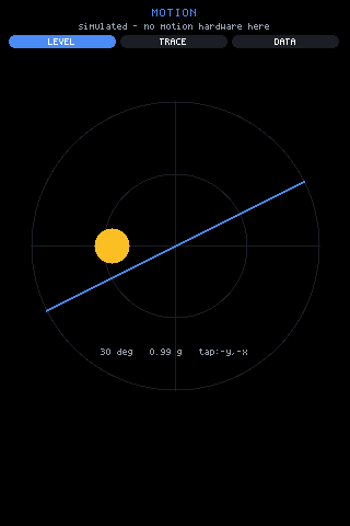
Section titled “Axes are not the display’s axes”The chip’s X/Y/Z have no fixed relationship to the screen’s. Which way the part is rotated against the glass differs per board, and again per display rotation, so there is no single correct mapping to hardcode. The example does not try — it offers all eight and lets a tap choose:
var MAPS = [ { n: 'x,y', f: function (a) { return { x: a.x, y: a.y }; } }, { n: 'x,-y', f: function (a) { return { x: a.x, y: -a.y }; } }, { n: '-x,y', f: function (a) { return { x: -a.x, y: a.y }; } }, { n: '-x,-y', f: function (a) { return { x: -a.x, y: -a.y }; } }, { n: 'y,x', f: function (a) { return { x: a.y, y: a.x }; } }, { n: 'y,-x', f: function (a) { return { x: a.y, y: -a.x }; } }, { n: '-y,x', f: function (a) { return { x: -a.y, y: a.x }; } }, { n: '-y,-x', f: function (a) { return { x: -a.y, y: -a.x }; } }];The default was measured on the glass, not derived:
/* Measured on the glass, not derived: the chip's X and Y are SWAPPED relative to the display. A flat board reads z = -1g so +Z points into the glass, and with the axes crossed that puts the chip's +X along the screen's vertical and +Y along its horizontal -- so the screen's x comes from -a.y and its y from -a.x. Boards whose chip sits rotated differently are one tap on the dial away. */var MAP_DEFAULT = 7; /* '-y,-x' */The choice persists per host in configStorage, so calibrating a board is
a one-time act rather than a startup ritual:
kids.push(h('box', { h: dial, onTap: function () { configStorage.set('lvl.map', '' + ((mapIdx() + 1) % MAPS.length)); UI._dirty = true; }}, levelNodes(a, cx, cy, R)));The other trap in that view is a layout one, and it is general: abs is
page-absolute, not parent-relative. A dial drawn at box coordinates and
“centred” with flex spacers lands wherever the page origin happens to be.
Every coordinate in the level view is computed against gfx.width() and
gfx.height() directly:
var top = narrow ? 84 : 92;var dial = Math.min(gfx.width() - (narrow ? 40 : 56), gfx.height() - top - (narrow ? 26 : 34));if (dial < 50) dial = 50;var R = dial >> 1;var cx = gfx.width() >> 1, cy = top + R;Conversely the sparkline uses no abs at all — line and path
measure zero height, so as ordinary flow children they draw from their own
box’s origin and stack correctly. Reaching for abs there painted the
graph over the header.
Developing with no hardware
Section titled “Developing with no hardware”No in-tree backend provides sys.modCtl (see
consistency.md) — it is a device native, and the
browser, sim, terminal and pure-js hosts have none of them. So every
example gates on typeof sys.x === 'function' and renders a fallback, and
the sensors example goes one step further: it drives the same state itself,
so the page is developable anywhere.
/* No hardware: drive the same state so the page is developable anywhere. Deliberately NOT started when the module is live -- a simulated needle next to a real one would be a lie. */if (!HAVE_IMU) { (function tick() { var ms = sys.millis(); UI.set({ accel: { x: Math.sin(ms / 900) * 0.5, y: Math.cos(ms / 1300) * 0.5, z: -0.86 }, gyro: { x: Math.sin(ms / 300) * 40, y: Math.cos(ms / 400) * 40, z: 0 }, temp: 24.5 }); UI.setTimer(tick, 200); /* a real driver re-arms exactly this way */ })();}Three things that make this a pattern worth copying rather than a debug hack:
- The simulator writes to the same state keys the module patches, so the views have no idea which is running.
- It is not started when the module is live. A simulated needle beside a real one is a lie, and half-real pages are how bad readings get shipped.
- It re-arms with
UI.setTimerexactly the way a real driver would, so the render path being exercised is the production one.
The page also says which of the two you are looking at, in the header
line under the title — INFO.imu + ' + ' + INFO.mag when live,
'simulated - no motion hardware here' when not. Every screenshot on this
page is the simulated path, because it was rendered headless.
Raw pins and raw bus
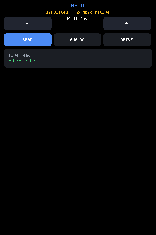
Section titled “Raw pins and raw bus”Below the module layer, sys.gpio(pin, op, value) and
sys.i2c(addr, reg, value) give a script direct hardware access. Their
full contract — op codes, return values, the per-board refused-pin lists —
is in hardware-api.md. The rules that matter most
when you are chasing a sensor:
- Reading a pin reconfigures it.
op 0setsINPUT_PULLUPon every call, so polling a pin you just drove releases it. An open pin reads 1, not 0 — that is the pullup, not a signal. - The display and touch pins are refused, with -1, from a denylist
built out of the same
config.hdefines that wire those peripherals. Reader UART pins are not refused, and driving them disturbs the PN532s. - The I2C bus is shared — with touch, and on the 3.5” board with the I/O expander, PMU, RTC and audio codec too. A read is usually harmless, though some devices clear interrupt flags on read; a stray register write to the PMU is not. Scan first, write only registers you know.
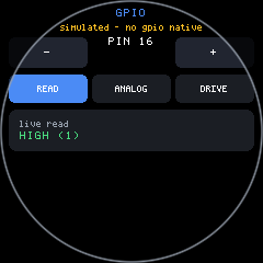
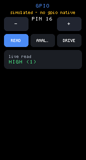
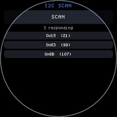
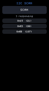
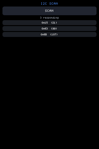
The scan’s shape is worth borrowing — a missing device NACKs quickly, but 112 probes inside one tap would still stall a frame:
/* A few addresses per tick: a missing device NACKs fast, but 112 probes in one tap would still stall a frame noticeably. */UI.onTick = function () { var next = UI.state.next; if (!HAVE || next === undefined || next === null) return; var found = UI.state.found || []; var stop = next + 8; for (; next < stop && next <= 119; next++) { if (sys.i2c(next, 0) >= 0) found = found.concat([next]); } UI.set({ found: found, next: next > 119 ? null : next });};Related: hardware-api.md for the pin and bus
contract, devices.md for the boards and the push/OTA
loop, round.md for the round board’s layout rules.